Adaptable Clearfloor 2 Post Car Lift VS. Floorplate 2 Post Car Lift, and How To Install A 2 Post Car Lift
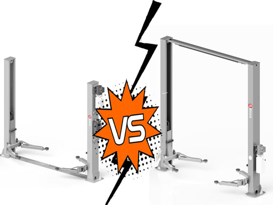
According to the different structures of the double post lift, there are clearfloor 2 post car lift and floorplate 2 post car lift, clearfloor 2 post car lift looks like the letter “n” from a distance, while floorplate 2 post car lift looks like the letter “u” from a distance. The clearfloor 2 post car lift looks like the letter “n” from a distance, while the floorplate 2 post car lift looks like the letter “u” from a distance. Both the floorplate and the clearfloor are synchronized to keep the car lifts running using wire ropes. Learn more about car 2 post car lift installation methods and requirements below.
1. Difference between clearfloor 2 post car lift and floorplate 2 post car lift
Clearfloor 2 post car lift is the oil pipe, steel wire rope are set up in the upper end of the column, the ground between the column is flat, the vehicle through the area without obstruction. Normal clearfloor 2 post car lift is a one-piece column, inverted cylinders, beam with roof crash limit, suitable for vehicle body not higher than 1600mm.
Floorplate 2 post car lift machine is oil pipe, wire rope in the ground between the two columns through, so the vehicle through the block area, because there is no restriction on the top, so there is no restriction on the car’s height. The maximum lifting height depends on the cylinder’s effective stroke and the ceiling’s height!
2. 2 Post Car Lift Installation Methods and Requirements
Installation tools:
2 Post Car Lift one, hydraulic oil 10kg, site need to have 380V or 220V power supply, impact drill (with Φ19 drill bit), bucket, sledgehammer, screwdriver (a word, cross), level, tape measure (7.5 meters), movable wrenches (12 ″), sharp-nosed pliers, spring pliers, plum wrenches: (8 #, 10 #, 13 #, 14 #, 17 #, 19 #, (24 #), strong pliers, hexagonal wrenches: (3 #, 5 #, 8 #), socket wrenches: (28 #)
All of the above tools are essential in the installation process, after preparing the tools, please inventory the two post car lifter accessories purchased from automotive equipment manufacturers.
Foundation and Power Requirements for 4 Ton Clearfloor 2 Post Car Lift and Floorplate 2 Post Car Lift:
1, a one-time infusion of concrete structure, the thickness of not less than 150mm and must not have reinforcing steel, must be completely dry before installation. 2, the strength of concrete must be greater than 3000PSI (about 210kg/cm2); measurement of the strength can be used to impact on the concrete floor drilling, drilling out of the cement powder is presented as a fine powdery strength to be qualified!
3, the installation of the ground must be flat, level, there shall be no cracks.
4, the power supply capacity must be greater than 2.2kw, wire diameter greater than 2.5mm, and must have a good grounding.
3. Installation steps for 4.0 ton 2 Post Car Lift:
1,Install the outer column fittings.
2,put the two columns parallel to the ground in the installation position, according to the condition of the installation site to determine the installation position of the power side column, in general, the power side column is installed in the direction of the right into the car; the lift column is designed as a two-stage type, according to the workshop height is different, the outer column and the inner column coupling position is different, when the height of the workshop is lower than 3850mm, the use of low-level installation: a set of holes above the outer column and the inner column When the height of the workshop is higher than 3850mm, it will be installed in high position: a set of holes below the outer column will be connected with the inner column.
3,Erect the column, install the ground screws, use the level ruler to measure whether the column is vertical, use the leveling pad to correct the vertical column. At this time, the ground screws do not need to be tightened.
4,Hooks on the top joint assembly are hung on the outer column to lock the screws, and then install the top joint slot.
5,Erect the column, install the ground screws, use a level to measure whether the column is vertical, use the leveling pad to correct the vertical column. At this time, the ground screw does not need to be tightened.
6,Hooks on the top joint assembly are hung on the outer column to lock the screws, and then install the top joint slot.
7, power side and non-power side of the safety mechanism accessories and wire rope installation, unlocking for the unilateral unlocking, power side with a press handle, non-power side without a handle, with automatic return spring pulley.
8,Lift up the lifting head, stuck in the same level of insurance position.
9,The low position of the wire rope installation connection, note: the wire rope should go to the inside of the lifting head.
10,The high position of the wire rope installation connection. Wire rope from the head down to wear up, wear out the head opening will be two wire rope nut interlocking.
11,Installation of hydraulic station and oil pipe. Hydraulic station screws first lock lift to the power column fixed slot locking screws, three-way valve and two-way valve to find out the oil pipe connected to the synchronization of the other side of the oil pipe connected to the cylinder and the hydraulic station above.
12,Installation of protective wire groove: oil pipe installation: both sides of the oil pipe installation schematic. (Note: oil pipe and small wire rope can not cross).
13,Safety mechanism wire rope, oil pipe and the installation of the protection line groove. The protection line groove above the outer column is fixed with M635 half-round head screws, and the protection line groove above the inner column is fixed with M640 half-round head screws. After all the above precautions are OK, you can install the protection wire channel. Will be covered by the slot in the column in order to use the cross flat head screws can be twisted tightly.
14, installed lifting arm; lifting head down to the lowest position, at this time with 8 # hexagonal wrench to loosen the fixed gear hexagonal screws, according to the direction of the arrow can be adjusted gear, until the gear and rack to achieve a good state of mesh and lock the screws, with 8 # hexagonal wrench to loosen the fixed gear hexagonal screws.
15, adjust the gear and rack meshing, gear and rack to achieve a good state of mesh with the hexagonal wrench to lock the screws.
16, tighten all the oil pipe joints, to the hydraulic station full of hydraulic oil (in order to ensure the service life of the hydraulic system and to ensure that the equipment operates to the best state, please fill 46 high quality anti-wear hydraulic oil).
17, single-phase (220V) hydraulic station motor wiring.
(1) the two lines of the external power line (fire line L and zero line N) were connected to the AC contactor labeled L1, L2 terminals.
(2) Hydraulic station motor in the two wires were connected to the AC contactor labeled T1, T2 terminals.
(3) Use a wire to connect the AC contactor A2 terminal to the L2 terminal.
(4) Connect the limit switch: first remove the wire connecting the 4# terminal on the push button switch and the A1 terminal on the AC contactor, then connect the 12# wire (brown wire) of the limit switch to the 4# terminal on the push button switch, 11# wire (blue wire) to the A1 terminal of the AC contactor, and then connect the ground wire (greenish-yellow wire) of the limit switch to the ground wire terminal in the motor junction box. Connect the ground wire (yellow-green wire) of the limit switch to the ground terminal in the motor junction box.
(5) Pushbutton switch 3# terminal is connected to AC contactor L1 terminal.
18, three-phase (380V) hydraulic station motor wiring:
(1) external power supply of three lines (L1, L2, L3) were connected to the AC contactor marked L1, L2, L3 terminals.
(2) Limit switch cable line 12 # line (brown line) connected to the button switch 4 # terminal, 11 # line (blue line) connected to the AC contactor A1 terminal, connected to the limit switch ground (yellow-green line) and the motor junction box ground terminal connection.
(3) Push-button switch 3# terminal connects to AC contactor L1 terminal.
19, Equipment debugging
(1) Adjustment of synchronized wire rope
Use an open-end wrench to hold the wire rope connector, and use a plum wrench to tighten the wire rope nut until the two synchronized wire ropes are adjusted to a certain tension and consistency. If the lifter does not run synchronously on both sides of the lifting head when it rises/falls, tighten the wire rope nut on the lower side of the lifting head until the lifter rises/falls in synchronized operation.
(2) Adjustment of safety mechanism wire rope
The two lifting heads will be lifted and stuck on the insurance, tighten the wire rope of the safety mechanism with force and then relax it a little, then tighten the tightening nut of the wire rope of the safety mechanism to ensure that the safety mechanism can always lock the lifting head safely and also open it flexibly to a safe state; finally, install the protective cover of the safety mechanism.
(3) Cylinder air exhaust
The hydraulic system is equipped with an exhaust screw, located in the top of the cylinder exhaust first lift the head to more than one meter, loosen the top of the cylinder screw plug (do not screw out all the screw plug), discharge the air in the system, and then tighten the screw plug. Then lift the head up and down until the equipment can run at the same speed without shaking. Otherwise, exhaust again.
(4) Adjustment of descending speed
Users can adjust the descending speed according to the demand, the method is: first loosen the throttle valve fixing nut, adjust the throttle valve bolt clockwise, then the descending speed becomes slower, and vice versa becomes faster. Don’t forget to tighten the fixing nut when adjusting to the required speed;
(5) Load test
After completing the above adjustments must be loaded test, test the first low running a few times, check the synchronization of the run and the card release insurance synchronization are consistent, and no other abnormalities and then run the whole process, such as any abnormalities need to repeat the above adjustments.
Tip: the first no-load operation will have a jittery phenomenon, loaded run a few times, to be removed from the hydraulic system after the natural elimination of air!
20, lowering the car
(1) Clean up the obstacles around and under the lifter, and let the people around leave.
(2) Press the rise button to lift the car slightly and pull the safety mechanism; then press the lowering manipulator handle to lower the car.
(3) Swing the lift arms toward the ends and shorten them to the shortest position.
(4) Drive away the automobile.


